Gas Chromatographs for Education and Industry
Thermal conductivity detector (TCD)
The detector of a chromatograph is meant to output an electronic signal when a component of the substance to be analysed emerges from the column. There are diverse methods of generating such electrical signals, one of them being the thermal conductivity detector described in the following.

Principle of the TCD
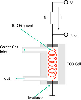
The ability of gases to conduct heat depends directly on the mass of their molecules. According to the kinetic theory of gases, light molecules are better conductors of heat than heavy ones. This fact is made use of by the TCD the Fig below showing its fundamental design. The carrier gas from the separation column flows through a cylindrical chamber containing a thin wire made of a tungsten alloy. This wire, or filament, has an electrical resistance R which depends on the temperature of the filament. In the case of metals, this resistance generally increases with the temperature. Such conductors are said to have a positive temperature coefficient (PTC). If a current I flows through the resistance, the voltage VDet through it is determined using Ohm's law:
VDet = R(T) • I
If a component with a higher molecular mass than that of the carrier gas emerges from the column, the heat from the heating filament is channelled off more slowly by the gas mixture. Consequently, the temperature T of the filament rises, and so does its electrical resistance. Given a constant current I, UDet also rises as a result. This configuration hence indicates changes in the composition of a carrier gas in the form of voltage variations.
However, one disadvantage of this simple detector is that any other extraneous factor influencing the temperature of the filament also influences the voltage UDet and is thus superimposed on the effective signal. Examples of such undesirable effects are:
- Change in the flow of gas
- Variations in the operating voltage
- Change in the ambient temperature
TCD with a reference cell
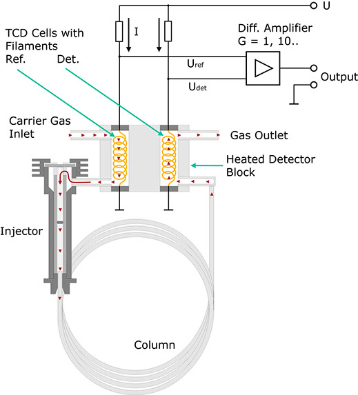
In practice therefore, the detector is not used in the form described above. The configuration shown here proves much more practical. In this case, the carrier gas flows through a second measurement cell before entering the injector. Both measurement cells are located together in a metal block possessing a high thermal conductivity.
Here too, the current I results in a voltage drop URef across the heating filament. In the absence of a test substance, UDet should be equal to URef if both the tungsten wires are identical and thus have the same resistance. The bridge voltage UDet-URef should be zero. This no longer applies on the emergence of a component from the column. Now a difference arises between UDet and URef. In a first approximation, this difference is proportional to the concentration of the expelled component. The voltage is amplified and recorded as a function of time.
Why is this detector much less sensitive to changes in the variables mentioned above? For example, let us assume that the ambient temperature rises. As the filaments are thermally coupled, this rise affects both of them in equal measure. Consequently, UDet and URef rise, the difference between these two values ideally remaining constant. Ideally speaking, changes in the flow of the carrier gas do not affect the bridge voltage either, as such changes influence the temperature of both filaments, i.e. UDet and URef change accordingly but the difference between them remains nearly constant.
Summary of the essential properties of a TCD:
- At low concentrations of foreign substances, the output signal is proportional to the concentration.
- The sensitivity of a TCD depends on the substances involved.
- The dimensions of the measurement cell of a TCD must remain above a certain limit. The minimum diameter of such cells is approx. 2 mm; the volume is relatively large for gas flows in standard capillary columns. A TCD can only be used successfully in conjunction with capillary columns if these columns have a sufficient width (e.g. 0.53 mm internal diameter) and high film thickness (e.g. 5 micrometers).
- TCDs are non-destructive, i.e. the eluted substances are not changed.
- TCDs are not particularly suitable for trace analysis.
- TCDs should only be used with carrier gases possessing a high thermal conductivity. Hydrogen and helium are suitable for this ppurpose.
- If the temperature of the column furnace has been programmed, the reference line can be expected to drift.
- In the hot state, the tungsten filaments of the TCD might be adversely affected through oxidation by oxygen in the carrier gas. This can happen, for example, if the flow of carrier gas has inadvertently not been turned on. On no account must the TCD be operated with air for extended periods!
Home
Contact us
Legal Notice
